In this blog post, we walk through diagnosing and repairing a no-power issue on an LG 42LB550V TV. The problem was isolated to the power supply board, and we cover the full repair process, including how to identify shorts and replace faulty components like the MOSFET.
🧪 Step-by-Step Diagnosis
🔌 1. Initial Check
-
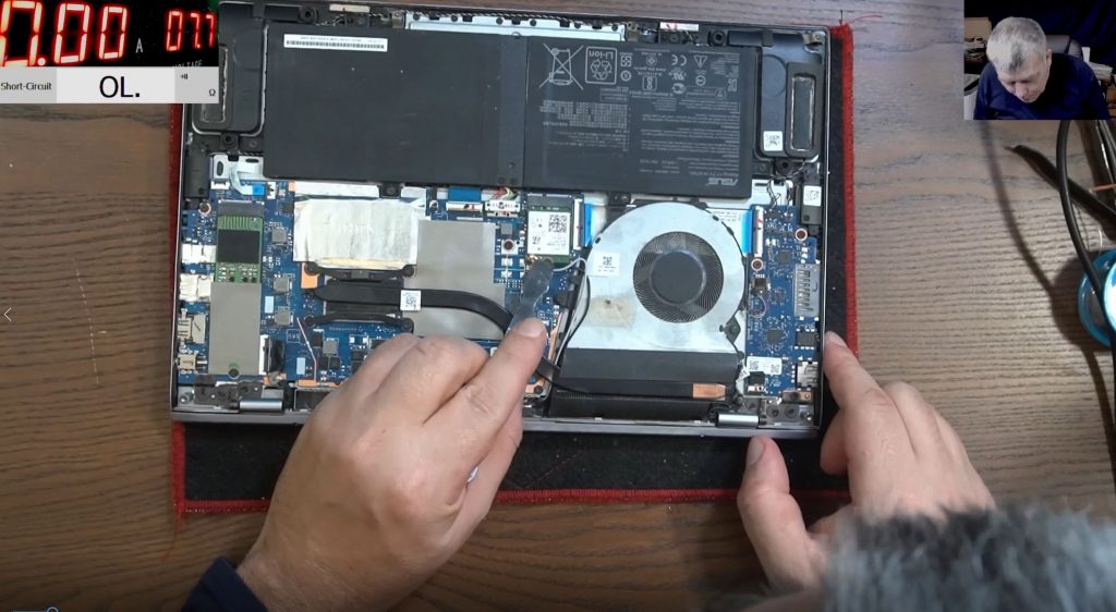
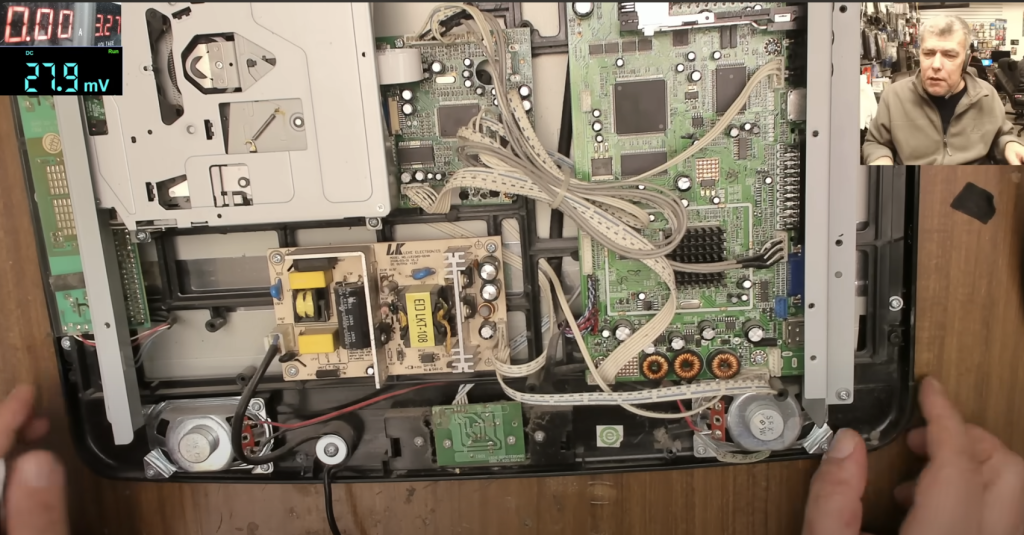
🖥️ Open the TV and remove the power supply board.
-
🔍 Test the fuse with a multimeter in diode mode.
-
⚠️ Important: If the fuse is blown, don’t just replace it — this usually means there’s a deeper fault like a short circuit.
💥 Replacing a fuse without diagnosing can lead to another blowout.
🔍 2. Identify Short on Rectifier Bridge
-
🔄 Circuit path:
AC input → Fuse → Thermistor → Filters → Rectifier Bridge -
🔌 Rectifier Pins:
-
Middle = AC input.
-
Outer = DC output (
+and–).
-
-
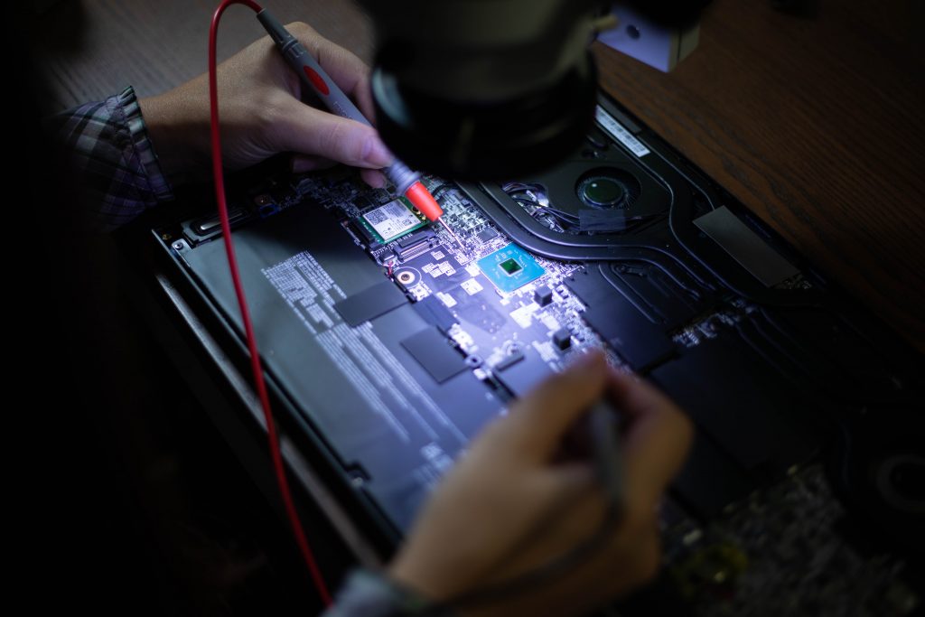
📏 Measure resistance across DC output:
-
0 ohms = direct short in the circuit.
-
✂️ 3. Isolate the Rectifier Bridge
-
🪛 Cut one of the DC pins (e.g.,
+) on the rectifier. -
⚡ Test again:
-
If the short is gone, ✅ the rectifier is not the issue.
-
🧭 4. Trace the Short
-
🔍 Follow the
+rail to locate components:-
⚙️ Diodes
-
⚡ Capacitors
-
🔲 MOSFETs
-
-
❗ A MOSFET near the transformer was suspected faulty.
🔄 MOSFET Testing and Replacement
🧪 1. Quick Test
-
✂️ Cut the middle pin (drain) of the MOSFET to isolate it.
-
🔎 Measure resistance between source and drain:
-
0 ohms = the MOSFET is shorted and must be replaced.
-
🔥 2. Remove the Faulty MOSFET
-
🧯 Desolder the heatsink (usually soldered to the board).
-
🔥 Use a high-wattage soldering iron to handle heat absorption.
-
🧼 Remove glue or thermal paste, then carefully remove the MOSFET.
🆗 3. Find a Replacement
-
🧾 Original Spec: 600V / 11A N-channel MOSFET.
-
🛠️ Replacement used: 500V / 12A, a close match.
⚠️ Specs don’t have to be identical, but they should be as close as possible or slightly higher.
🛠️ 4. Install the New MOSFET
-
🔩 Secure the new MOSFET and solder all pins.
-
🔗 If a pin is short, use a piece from the old MOSFET to bridge the connection.
-
🧊 Reattach the heatsink and ensure firm contact.
🧪 Testing the Repair
🔋 1. Install New Fuse
-
Use a 5A fuse for safe testing.
-
🛑 Never exceed the fuse rating.
💡 2. Power On
-
🔌 Plug in the TV.
-
📺 If screen turns on, the issue is fixed!
✅ In this repair, the TV powered on successfully, confirming the MOSFET replacement worked.
🧠 Key Takeaways
| 🔧 Step | ✅ Action |
|---|---|
| 📏 Test | Fuse and rectifier bridge |
| ✂️ Cut | Pins to isolate components |
| 🔥 Use | Proper soldering tools |
| 🆚 Match | Voltage/Current specs on MOSFETs |
| 💡 Power | Test with proper fuse |
💡 Final Tips
-
⚠️ Blown fuses often mean shorted components.
-
📈 Use an oscilloscope if you suspect gate driver issues.
-
🛠️ Matching replacement components is key to long-term reliability.